ARCHITECTURE OF 8085 MICROPROCESSOR:

Accumulator:-
It is a 8-bit register which is used to perform airthmetical and logical operation. It stores the output of any operation. It also works as registers for i/o accesses.
Temporary Register:-
It is a 8-bit register which is used to hold the data on which the acumulator is computing operation. It is also called as operand register because it provides operands to ALU.
Registers:-
Registers:-
These are general purposes registers. Microprocessor consists 6 general purpose registers of 8-bit each named as B,C,D,E,H and L. Generally theses registers are not used for storing the data permanently. It carries the 8-bits data. These are used only during the execution of the instructions.
These registers can also be used to carry the 16 bits data by making the pair of 2 registers. The valid register pairs available are BC,DE HL. We can not use other pairs except BC,DE and HL. These registers are programmed by user.
 \
\
ALU:-
ALU performs the airthmetic operations and logical operation.
Flag Registers:-
It consists of 5 flip flop which changes its status according to the result stored in an accumulator. It is also known as status registers. It is connected to the ALU.
1.Sign(S)
2.zero(z)
3.Auxiliary carry(AC)
4.Parity(P)
5.Carry(C)
The bit position of the flip flop in flag register is:
All of the three flip flop set and reset according to the stored result in the accumulator.
1.Sign-
If D7 of the result is 1 then sign flag is set otherwise reset. As we know that a number on the D7 always desides the sign of the number.
if D7 is 1: the number is negative.if D7 is 0: the number is positive.
2.Zeros(Z)-
If the result stored in an accumulator is zero then this flip flop is set otherwise it is reset.
3.Auxiliary carry(AC)-
If any carry goes from D3 to D4 in the output then it is set otherwise it is reset.
4.Parity(P)-
If the no of 1's is even in the output stored in the accumulator then it is set otherwise it is reset for the odd.
5.Carry(C)-
If the result stored in an accumulator generates a carry in its final output then it is set otherwise it is reset.
Instruction registers(IR):-It is a 8-bit register. When an instruction is fetched from memory then it is stored in this register.
Instruction Decoder:- Instruction decoder identifies the instructions. It takes the informations from instruction register and decodes the instruction to be performed.
Program Counter:-
It is a 16 bit register used as memory pointer. It stores the memory address of the next instruction to be executed. So we can say that this register is used to sequencing the program. Generally the memory have 16 bit addresses so that it has 16 bit memory.The program counter is set to 0000H.
Stack Pointer:-
It is also a 16 bit register used as memory pointer. It points to the memory location called stack. Generally stack is a reserved portion of memory where information can be stores or taken back together.
Timing and Control Unit:-
It provides timing and control signal to the microprocessor to perform the various operation.It has three control signal. It controls all external and internal circuits. It operates with reference to clock signal.It synchronizes all the data transfers.
There are three control signal:
1.ALE-Airthmetic Latch Enable, It provides control signal to synchronize the components of microprocessor.
2.RD- This is active low used for reading operation.
3.WR-This is active low used for writing operation.
There are three status signal used in microprocessor S0, S1 and IO/M. It changes its status
according the provided input to these pins.

Serial Input Output Control-
There are two pins in this unit. This unit is used for serial data communication.
Interrupt Unit-
There are 6 interrupt pins in this unit. Generally an external hardware is connected to these pins. These pins provide interrupt signal sent by external hardware to microprocessor and microprocessor sends acknowledgement for receiving the interrupt signal.Generally INTA is used for acknowledgement.
PIN DIAGRAM OF 8085 MICROPROCESSOR :
8085 is a general purpose microprocessor having 40 pins and works on single power supply. To study the pin diagram we group
the signals into 5 categories:
1.Power Supply
2.Clock Signals
3.Interrupt Signals
4.Address and Data bus
5.Control and Status signals
6.Serial I/O Port
7.DMA Request Signals
the signals into 5 categories:
1.Power Supply
2.Clock Signals
3.Interrupt Signals
4.Address and Data bus
5.Control and Status signals
6.Serial I/O Port
7.DMA Request Signals

Power Supply Signal and clock signal:
VCC:-
Vcc is to be connected to +5V power supply.
Vss:-
Ground reference
X1 and X2:-
This pin is used for providing the clock frequency to the microprocessor. Generally Crystal oscillator or LC oscillator is used to generate the frequency. The frequency generated here is internally divided into two.As we know that the basic operating timing frequency of the microprocessor is 3 MHz so
6 MHz frquency is applied.
Serial Input Output port:-
6 MHz frquency is applied.
Serial Input Output port:-
SID and SOD:-
These pins are used for serial data communication.
Interrupt Signal:-
Interrupt Signal:-
Pin 6 to 11:-
These pins are used for interrupt signals. Generally and external devices are connected here which requests the microprocessor to perform a particular task.
There are 5 pins for hardware interrupts-
TRAP, RST7.5, RST 6.5, RST5.5 and INTR
INTA is used for acknowledgement. Microprocessor sends the acknowledgement to external devices through the INTA pin.
Address Bus and DATA Buses:-
There are 5 pins for hardware interrupts-
TRAP, RST7.5, RST 6.5, RST5.5 and INTR
INTA is used for acknowledgement. Microprocessor sends the acknowledgement to external devices through the INTA pin.
Address Bus and DATA Buses:-
AD0-AD7:-
These are multiplexed address and data bus. So it can be used to carry the lower order 8 bit address as well as the data. Generally these lines are demultiplexed using the Latch.
During the opcode fetch operation, in the first clock cycle the lines deliever the lower order address bus A0-A7.
In the subsequent IO/M read or write it is used as data bus D0-D7. CPU can read or write data through these lines.
A8-A15:-
During the opcode fetch operation, in the first clock cycle the lines deliever the lower order address bus A0-A7.
In the subsequent IO/M read or write it is used as data bus D0-D7. CPU can read or write data through these lines.
A8-A15:-
These are address bus used to address the memory location.
Control And Status Signal:-
S0 and S1:-
It is used for the status signal in microprocessor.
ALE(Airthmetic Latch Enable):-
ALE(Airthmetic Latch Enable):-
This signal is used to capture the lower address presented on multiplexed address and data bus.
RD:-
RD:-
This is active low input generally used for reading operation.
WR:-
WR:-
This is active low input used for writing operation.
IO/M:-
IO/M:-
This pin is used to select the memory or input-output through which we want to communicate the data.
READY:-
READY:-
As we know that memory and input -output have slower response than microprocessor. So a microprocessor may now be able to handle further data till it completes the present job. So it is in waiting state. As it completes the present job it sets the READY pin. Microprocessor enters into wait state while READY pin is disabled.
RESET IN:-
This is active low input. This pin is used to reset the microprocessor. An active low signal applied to this pin reset the program counter inside the microprocessor. The busses are tristated.
RESETOUT:-
If we want to reset the external devices connected to the microprocessor then a signal applied to this pin resets the external devices.
DMA Request Signal:
DMA Request Signal:
HOLD and HLDA:-
HOLD is an active high input signal used by the other controller to request microprocessor about use of address, data and control signal. The HOLD and HLDA signal are used for direct memory access(DMA). DMA controller receives a requests from a device and in turn issues the HOLD signal to the microprocessor.
The processor releases the system bus and then acknowledges the HOLD signal with HLDA signal. The DMA transfer thus begins.
The processor releases the system bus and then acknowledges the HOLD signal with HLDA signal. The DMA transfer thus begins.
ADC DAC CONVERTERS:
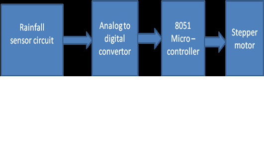
Data Conversion Devices are very important components of a Machine Control Unit (MCU). MCUs are controlled by various computers or microcontrollers which are accepting signals only in Digital Form i.e. in the form of 0s and 1s, while the signals received from signal conditioning module or sensors are generally in analog form (continuous). Therefore a system is essentially required to convert analog signals into digital form. Analog to Digital Converter is abbreviated as ADC. Figure shows a typical control system with data conversion devices.
Based on the signals received from sensors, MCU generates actuating signals in the Digital form. Most of the actuators e.g. DC servo motors only accept analogue signals. Therefore the digital signals must be converted into Analog form so that the required actuator can be operated accordingly. For this purpose Digital to Analog Converters are used, which are abbreviated as DACs.
.png) |
| A control system with ADC and DAC devices
Basic components used in ADCs and DACs:
In general ADCs and DACs comprise of Comparators. Comparator is a combination of diodes and Operational Amplifiers. A comparator is a device which compares the voltage input or current input at its two terminals and gives output in form of digital signal i.e. in form of 0s and 1s indicating which voltage is higher. If V+ and V- be input voltages at two terminals of comparator then output of comparator will be as
V + > V - → Output 1
V + < V - → Output 0
|
2. Encoders:
Though the output obtained from comparators are in the form of 0s and 1s, but can't be called as binary output. A sequence of 0s and 1s will be converted into binary form by using a circuit called Encoder. A simple encoder converts 2n input lines into ‘n' output lines. These ‘n' output lines follow binary algebra.
3. Analog to Digital Converter (ADC):
1.Direct Conversion ADC:
.png) |
| Circuit of ADC |
Above Figure shows the circuit of Direct conversion. To convert a digital signal of N-bits, ADC requires 2N -1 comparators and 2N resistors. The circuit provides the reference voltage to all the comparators. Each comparator gives an output of 1 when its analog voltage is higher than reference voltage or otherwise the output is 0. In the above circuit, reference voltages to comparators are provided by means of resistor ladder logic.
The circuit described in figure acts as 3 Bit ADC device. Let us assume this ADC works between the range of 0-10 Volts. The circuit requires 7 comparators and 8 resisters.Now the voltages across each resistor are divided in such a way that a ladder of 1 volt is built with the help of 1K-Ohm resistances. Therefore the reference voltages across all the comparators are 1-7 volts.
Now let us assume that an input voltage signal of 2.5 V is to be converted into its related digital form. As 2.5V is greater than 1V and 2V, first two comparators will give output as 1,1. But 2.5V is less than 3,4,5,6,7 V values therefore all other comparators will give 0s. Thus we will have output from comparators as 0000011(from top). This will be fed to the encoder logic circuit. This circuit will first change the output in single high line format and then converts it into 3 output lines format by using binary algebra. Then this digital output from ADC may be used for manipulation or actuation by the microcontrollers or computers.

Digital to Analog Converters:
1 Binary Weighted DAC:
 |
| Circuit of binary weighted DAC |
 |
| An op-amp used in DAC |
As name indicates, in binary weighted DAC, output voltage can be calculated by expression which works on binary weights. Its circuit can be realized in Figure . From the figure it can be noted that most significant bit of digital input is connected to minimum resistance and vice versa. Digital bits can be connected to resistance through a switch which connects resistance-end to the ground . The digital input is zero when former bit is connected to reference voltage and if it is 1. This can be understood from Figure . DAC output voltage can be calculated from property of operational amplifiers. If V1 be input voltage at MSB (most significant bit), V2 be input voltage at next bit and so on then for four bit DAC we can write,
 |
Here V1, V2, V3, V4, will be Vref if digital input is 1 or otherwise it will be zero.
Hence output voltage can be found as:
However Binary weighted DAC doesn't work for multiple or higher bit systems as the value of resistance doubles in each case.
Thus simple and low bit digital signals from a transducer can be converted into a related continuous value of voltages (analogue) by using binary weighted DAC. These will further be used for manipulation or actuation.
2.R-2R Ladder based DAC:
 |
| R-2R Ladder based DAC |
n R-2R ladder logic, shortcoming of Binary Logic has been removed by making the value of maximum resistance double however the rest of the circuit remains same.Figure 2.8.5 shows the circuit of R-2R Ladder based DAC. If we apply voltage division rule in above case, then we can calculate that output voltage as,
 |
Where VAL can be calculated from the digital signal input as,

In this way output voltage is obtained by converting the digital signals received from microprocessor/ microcontroller. These voltages will further be used to actuate the desired actuator viz. DC/AC motors.
In this module we have studied the principle of operation of various sensors which are commonly used in mechatronics and manufacturing automation. Also the signal conditioning operations and the devices which are used to generate the proper signals for desired automation application have been studied. In the next module we will study the construction and working of microprocessor and the devices which are being used in controlling the various operations of automation using the microprocessors. |